More and more often, Variable Frequency Drives (VFDs) are used for control of fans and compressors in HVACR systems. The benefits are well documented and industry acceptance is such that most electric utilities offer substantial monetary incentives (rebates) when they are used.
Federal, state and some local governments are also cognizant of the efficiency gains realized from VFD use and offer incentives, grants or low/no interest loans to help.
This article specifically compares three schemes of fan control used on large air conditioning and refrigeration condensers. The first scheme is step control; the second is a hybrid with a VFD on only one bank of fans, while the rest remain step controlled. The final, and most efficient, scheme is VFD control of all fans, at all times.
Bear in mind that the actual CFM, amps and watt numbers shown are for a specific test application. These values will be different on other systems, but the calculations and curves in the graphs will look similar.
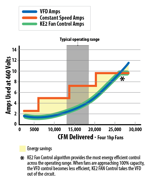
Figure 1 presents the baseline for illustrating the efficiency gains possible by using VFDs, sometimes referred to as Variable Speed Drives (VSDs).
Figure 1 – Efficiency Gains Possible Using VFDs

Staged Control
Historically, fans or banks of fans, were staged on in response to changes in head pressure or ambient temperature. Individual pressure controls were used for each bank of fans, and a pressure rise of ~ 20 psi was required to bring on the next fan or bank of fans. Head pressure control was poor because each increase in heat rejection load caused a significant rise in head pressure.
Energy efficiency was also poor. Each time a bank of fans was started across-the-line, the system saw a high inrush current. Since the capacity added by each bank of fans may not have been needed, fans were staged on and off frequently. Depending on the electricity supplier, these inrush currents may have affected utility rates paid by the owner.
Frequent, full speed, starts and stops shorten the life of the fan motor, so along with running costs, maintenance costs were high.
More importantly, staged fan control leads to jumps in the power consumed rather than the smoothly increasing power used to match actual heat of rejection increases in the condenser.
VFD Control
There are two basic means of using variable speed control on condenser fans. In the first type, most fans will be staged on and run at full speed while one bank of fans is speed controlled, primarily for trim of head pressure.
While somewhat effective, and usually less expensive, energy consumption is not much better than old-fashioned step control.
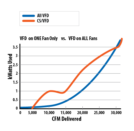
Figure 2 – Power Used for CFM Delivered

Figure 2 shows power used for various CFM requirements using this method. In this example, the maximum system requirement is 31,000 CFM. Full capacity requires all fans to run at full speed and each of 4 fans can deliver 7,750 CFM.
As air flow requirements are reduced, fans are staged off. For 31,000 CFM, all four fans must run at full speed whether on the VFD or CS (Constant Speed direct across-the-line run). Since the CS fans always produce the same air flow, some number of them will run until flow requirements drop enough to have them stage off. During this staging process, the VFD will run the first fan bank, at various speeds, to make up the difference. Table 1 shows the CS flow for each stage and the required balance of flow from the VFD.
Table 1 – Fan Staging and Speed for Various CFM
| Total CFM | # CS fans | CS fan CFM | VFD CFM |
|---|---|---|---|
31000 | 4 | 31,000 | 0 |
30000 | 3 | 23,250 | 6750 |
25000 | 3 | 23,250 | 1750 |
20000 | 2 | 15,500 | 4500 |
15000 | 1 | 7,750 | 7250 |
10000 | 1 | 7,750 | 2250 |
5000 | 0 | 0 | 5000 |
Figure 2 uses this data and the Fan Affinity laws to calculate the power used, in kW, for each condition of air flow. Basic power, speed and CFM were measured on a real unit and the rest of the data derived from the equations:
1) cfm2 = (rpm2/rpm1) x cfm1
and
2) hp2 = (rpm2/rpm1)³ x hp1
Equation 1 states that change in air flow (cfm) is directly proportional to the speed of the fan. In other words, doubling the fan speed doubles the air flow. Obviously, it works in both directions so that if half the cfm is required, the fans need only run at half speed.
Equation 2 shows the real advantage of changing fan speed to save substantial amounts of energy. The power used increases as the cube of the fan speed. This means that doubling the fan speed (speed x 2) will increase power used by a factor of 8 (2x 2 x2).
Since Equation 1 states the CFM is proportional to speed, the following equation, where CFM is substituted for speed, is valid.
3) hp2 = (cfm2/cfm1)³ x hp1
Of course, this works in both directions, too. Half the cfm will only need 1/8th of the power.
In Figure 1, the amp draw for step control and VFD control were shown separately on the same graph. Figure 2 shows the power used when all fans run on the VFD and another curve showing power used in the design that uses the VFD on only one bank of fans.
Referring again to Figure 2, when all fans run on the VFD only (blue line), the power used increases at a smooth rate, related to the CFM, in accordance with the Fan Affinity Laws. Of course, power used does not drop to 0 until air flow does; the scale of the graph just makes it appear so.
The odd characteristic of the CS/VFD curve illustrates the fact that every time a bank of fans is turned on, the fans will run at full speed and the power used will increase by the full consumption of that bank. However, the VFD will take up the slack between stages and modify the step curve that was shown in Figure 1.
The difference between the two curves represents the energy saved by using VFD control on all fans, rather than just using speed control on one bank and step control on the rest.
Fan Quantity
Once VFD control of all fans is adopted, the next question concerns the number of fans to use. Ordinarily, the number of fans on a condenser is based on total heat of rejection and is fixed by the size of the unit. However, there are instances where the capacity of two condensers is the same, but one has fewer, larger fans than the other. This may be done for economy of first cost or footprint limitations, but there should be consideration given to operating cost, too.
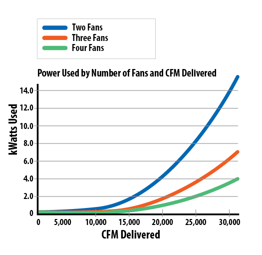
Figure 3 shows the power consumption of three condensers supplying the same CFM. To obtain the same air flow with fewer fans means that each fan must run faster, other things being equal. As shown previously, when the speed or air flow of the fan doubles, the power used increases by a factor of 8.
Figure 3 – Power Consumption Comparison
 The condenser with 2 fans (blue line) must run the fans at a much higher speed, and draw more power. The condenser with 3 fans (red line) is more efficient, and the unit with 4 fans is most efficient. Certainly, there is an argument to be made that if fewer fans are used, they would be larger, perhaps more efficient and run at a lower speed. But literature of a major condenser manufacturer shows that for ~60,000 CFM, either a 12 fan unit with a power draw of 5.2 kW or an 8 fan unit drawing 8.9-10.8 kW can be used. Similarly, ~30,000 CFM can be reached with a 6 fan unit at 2.6 kW or a 4 fan unit at 4.5-5.4 kW. There are, of course, other variations in the units, but the trend is clear. Given a choice of fewer, larger or more, smaller fans, the better choice is to use more, smaller fans.
Thermal Shock
A final reason to use VFDs for all the fans on a condenser has nothing to do with energy use at all. Instead, total VFD fan control has advantages in maintenance and even refrigerant charge. Condensers are subject to extreme temperature changes both internally and externally. Hot discharge gas may enter at over 200°F and leave as liquid at 100°F, or cooler. The temperature differences inside the condenser coil, and between the ambient and the condenser coil, may lead to differential thermal expansion or thermal shock.
Most modern condensers have some means of minimizing the damage that may result from thermal shock. Floating tube sheets, special return bends or laser cut expansion slots are all used effectively. However, during cool or cold ambients, when a fan is staged on, it immediately blows a high volume of cold air across a hot coil. This may cause parts of the coil to contract differently from other parts of the condensing coil. This, in turn, causes additional mechanical stress on the entire coil and may lead to premature failure of the tubing or return bends, and complete loss of the refrigerant charge. Loss of charge is not only expensive and damaging to the system, but adds more refrigerant to the atmosphere, with all the related issues and environmental impact.
By controlling all fans with a VFD, the fan speeds, and air flow, will all ramp up and down equally across the entire face of the coil. Cold spots, differential expansion and contraction, and mechanical stress are all minimized. Condensers may last longer, and be less subject to catastrophic failures and refrigerant loss.
It is accepted fact that VFDs save energy and that fact is backed up by laws of physics and supported by suppliers of energy, in the form of rebates. Using VFD control is a good idea, but how they are used has a great effect on system efficiency and longevity.
To maximize energy efficiency and improve condenser life, the best design is to use more, smaller fan motors, and control all together with a VFD.
